技术特性 Features
- 3-phase IGBT inverter bridge configured by the latest 3rd.generation IGBT and diode technologies.
- Circuit for dynamic braking of motor regenerative energy.
- Inverter output current capability IO (Note 1):
Type Name |
100% load |
150% over load |
PS11016 |
11.0A (rms) |
16.5A (rms), 1min |
(Note 1) : The inverter output current is assumed to be sinusoidal and the peak current value of each of the above loading cases is defined as : IOP = IO ´ Ö`2
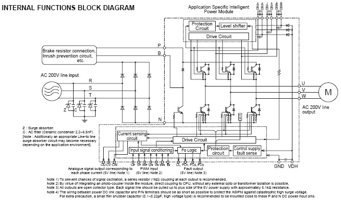
综合功能 INTEGRATED FUNCTIONS
- For P-Side IGBTs : Drive circuit, High voltage isolated high-speed level shifting, Short-circuit protection (SC),
Bootstrap circuit supply scheme (Single drive-power-supply) and Under voltage protection (UV).
- For N-Side IGBTs : Drive circuit, Short circuit protection (SC), Control-supply Under voltage and Over voltage protection (OV/UV), System
Over-temperature protection (OT), Fault output (FO) signaling circuit, and Current-Limit warning signal output(CL)
- For Brake circuit IGBT : Drive circuit
- Warning and Fault signaling :
FO1 : Short circuit protection for lower-leg IGBTs and Input interlocking against spurious arm shoot-through.
FO2 : N-side control supply abnormality locking (OV/UV)
FO3 : System over-temperature protection (OT).
CL : Warning for inverter current overload condition
- For system feedback control : Analogue signal feedback reproducing actual inverter phase current (3f).
- Input Interface : 5V CMOS/TTL compatible, Schmitt trigger input, and Arm-Shoot-Through interlock protection.
订购信息 Ordering Information
应用领域 APPLICATION
Acoustic noise-less 2.2kW/AC200V class 3 phase inverter and other motor control applications
功能框图 Functional Block Diagram

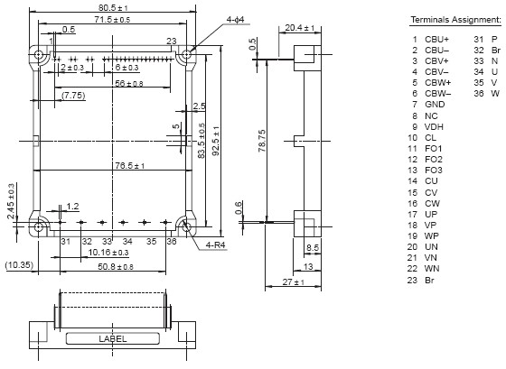
外观尺寸图 Outline Drawing

|


