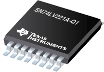
SN74LV221A-Q1 汽车类双路单稳多频振荡器

The SN74LV221A is a dual multivibrator designed for 2-V to 5.5-V VCC operation. Each multivibrator has a negative-transition-triggered (A) input and a positive-transition-triggered (B) input, either of which can be used as an inhibit input.
This edge-triggered multivibrator features output pulse-duration control by three methods. In the first method, the A input is low and the B input goes high. In the second method, the B input is high and the A input goes low. In the third method, the A input is low, the B input is high, and the clear (CLR) input goes high.
The output pulse duration is programmable by selecting external resistance and capacitance values. The external timing capacitor must be connected between Cext and Rext/Cext(positive) and an external resistor connected between Rext/Cext and VCC. To obtain variable pulse durations, connect an external variable resistor between Rext/Cext and VCC. The output pulse duration also can be reduced by taking CLR low.
Pulse triggering occurs at a particular voltage level and is not related directly to the transition time of the input pulse. The A, B, and CLR inputs have Schmitt triggers with sufficient hysteresis to handle slow input transition rates with jitter-free triggering at the outputs.
Once triggered, the outputs are independent of further transitions of the A and B inputs and are a function of the timing components, or the output pulses can be terminated by the overriding clear. Input pulses can be of any duration relative to the output pulse. Output pulse duration can be varied by choosing the appropriate timing components. Output rise and fall times are TTL compatible and independent of pulse duration. Typical triggering and clearing sequences are illustrated in the input/output timing diagram.
The variance in output pulse duration from device to device typically is less than ±0.5% for given external timing components. An example of this distribution for the SN74LV221A-Q1 is shown in Figure 8. Variations in output pulse duration versus supply voltage and temperature are shown in Figure 5.
During power up, Q outputs are in the low state, and Q outputs are in the high state. The outputs are glitch free, without applying a reset pulse.
This device is fully specified for partial-power-down applications using Ioff. The Ioff circuitry disables the outputs, preventing damaging current backflow through the devices when they are powered down.
Pin assignments are identical to those of the SN74AHC123A and SN74AHCT123A devices, so the SN74LV221A-Q1 can be substituted for those devices not using the retrigger feature
| SN74LV221A-Q1 | |
| Rating | Automotive |
| Technology Family | LV-A |
SN74LV221A-Q1 特性
- Qualified for Automotive Applications
- 2-V to 5.5-V VCC Operation
- Supports Mixed-Mode Voltage Operation on All Ports
- Schmitt-Trigger Circuitry on A, B, and CLR Inputs for Slow Transition Rates
- Overriding Clear Terminates Output Pulse
- Glitch-Free Power-Up Reset on Outputs
- Ioff Supports Partial-Power-Down Mode Operation
SN74LV221A-Q1 芯片订购指南
| 器件 | 状态 | 温度 | 价格(美元) | 封装 | 引脚 | 封装数量 | 封装载体 | 丝印标记 |
| SN74LV221AQPWRG4Q1 | ACTIVE | -40 to 125 | 0.95 | 1ku | TSSOP (PW) | 16 | 2000 | |
| SN74LV221AQPWRQ1 | ACTIVE | -40 to 125 | 0.95 | 1ku | TSSOP (PW) | 16 | 2000 |
SN74LV221A-Q1 质量与无铅数据
| 器件 | 环保计划* | 铅/焊球涂层 | MSL 等级/回流焊峰 | 环保信息与无铅 (Pb-free) | DPPM / MTBF / FIT 率 |
| SN74LV221AQPWRG4Q1 | Green (RoHS & no Sb/Br) | CU NIPDAU | Level-1-260C-UNLIM | SN74LV221AQPWRG4Q1 | SN74LV221AQPWRG4Q1 |
| SN74LV221AQPWRQ1 | Green (RoHS & no Sb/Br) | CU NIPDAU | Level-1-260C-UNLIM | SN74LV221AQPWRQ1 | SN74LV221AQPWRQ1 |
SN74LV221A-Q1 应用技术支持与电子电路设计开发资源下载
- SN74LV221A-Q1 数据资料 dataSheet 下载.PDF
- TI 德州仪器特殊逻辑产品选型与价格 . xls
- Shelf-Life Evaluation of Lead-Free Component Finishes (PDF 1305 KB)
- Understanding and Interpreting Standard-Logic Data Sheets (PDF 857 KB)
- TI IBIS File Creation, Validation, and Distribution Processes (PDF 380 KB)
- Implications of Slow or Floating CMOS Inputs (PDF 101 KB)
- CMOS Power Consumption and CPD Calculation (PDF 89 KB)
- Designing With Logic (PDF 186 KB)
- Live Insertion (PDF 150 KB)
- Input and Output Characteristics of Digital Integrated Circuits (PDF 1708 KB)
- Using High Speed CMOS and Advanced CMOS in Systems With Multiple Vcc (PDF 43 KB)
- HiRel Unitrode Power Management Brochure (PDF 206 KB)
- LOGIC Pocket Data Book (PDF 6001 KB)
- HiRel Unitrode Power Management Brochure (PDF 206 KB)
- Logic Cross-Reference (PDF 2938 KB)
